Stabilizer
Overview
Stabilizer is a flexible tool designed for quantum physics experiments. Fundamentally, Stabilizer samples up two two analog input signals, performs digital signal processing internally, and then generates up to two output signals.
Stabilizer firmware supports run-time configuration of the internal signal processing algorithms, which allows for a wide variety of experimental uses, such as digital filter design or implementation of digital lockin schemes.
This documentation is intended to bring a user up to speed on using Stabilizer and the firmware provided by QUARTIQ and contributors.
Hardware
The Stabilizer hardware is managed via a separate repository. Some information about the hardware is gathered in the Stabilizer wiki. More detailed data, measurements, discussions, and tests have been posted in the Stabilizer hardware and firmware issue trackers.
Stabilizer can be extended and coupled with a mezzanine board. One such mezzanine is the DDS upconversion/downconversion frontend Pounder. The Pounder hardware is managed via a separate repository, again with wiki and issue tracker.
Stabilizer can also control downstream EEM modules, for example Urukul-AD9912.
Applications
This firmware offers a library of hardware and software functionality targeting the use of the Stabilizer hardware in various digital signal processing applications commonly occurring in Quantum Technology.
It provides abstractions over the fast analog inputs and outputs, time stamping, Pounder DDS interfaces and a collection of tailored and optimized digital signal processing algorithms (IIR, FIR, Lockin, PLL, reciprocal PLL, Unwrapper, Lowpass, Cosine-Sine, Atan2) in the idsp crate.
An application, which is the compiled firmware running on the device, can compose and configure these hardware and software components to implement different use cases.
Several applications are provided by default.
The following documentation links contain the application-specific settings and telemetry information.
| Application | Description |
|---|---|
dual-iir | Two channel biquad IIR filter |
lockin | Lockin amplifier support various various reference sources |
dds | Urukul-AD9912 control over MQTT |
fls | Fiber length stabilizer/Phase-Frequency Metrology and control |
mpll | Dispersive PLL |
Library Documentation
The Stabilizer library docs contain documentation for common components used in all Stabilizer applications.
The Stabilizer library documentation is available here.
Setup
The Stabilizer firmware consists of different applications tailored to different use cases. Only one application can run on the device at a given time. After receiving the Stabilizer hardware, you will need to choose, build, and flash one of the applications onto the device.
Power
Power Stabilizer through exactly one of the following mechanisms.
- Via the backside 12V barrel connector
- Via Power-over-Ethernet using a PoE capable switch (802.3af or preferrably 802.3at) and the RJ45 front panel port
- Via an EEM connection to Kasli
Note: Applying power through more than one mechanism may lead to damage. Ensure the two unused methods are not connected or explicitly disabled.
Network and DHCP
Stabilizer supports 10Base-T or 100Base-T with Auto MDI-X.
Stabilizer uses DHCP to obtain its network configuration information. Ensure there is a properly
configured DHCP server running on the network segment that Stabilizer is connected to. If a DHCP
server is not available and a static IP is desired, Stabilizer can be configured with a static IP
via the USB interface. A configured ip of "0.0.0.0" will use DHCP.
Note: If Stabilizer is connected directly to an Ubuntu system (for example using a USB-Ethernet dongle) you can set the IPv4 settings of this Ethernet connection in the Ubuntu network settings to "Shared to other computers". This will start and configure a DHCP server for this connection.
MQTT Broker
Stabilizer requires an MQTT broker that supports MQTTv5. The MQTT broker is used to distribute and exchange elemetry data and to view/change application settings. The broker must be reachable by both the host-side applications used to interact with the application on Stabilizer and by the application running on Stabilizer. The broker must be reachable on port 1883 on that IP address - it may either be an IP address or a fully qualified domain name. Firewalls between Stabilizer and the broker may need to be configured to allow connections from Stabilizer to that port and IP address.
Mosquitto has been used as a MQTT broker during development, but any MQTTv5 broker without authentication or encryption will likely work.
Note: Mosquitto version 1 only supports MQTTv3.1. If using Mosquitto, ensure version 2.0.0 or later is used.
We recommend running Mosquitto through Docker to easily run it on
Windows, Linux, and OSX. After docker has been installed, run the following command from
the stabilizer repository to create a container named mosquitto that can be stopped
and started easily via docker:
# Bash
docker run -p 1883:1883 --name mosquitto -v `pwd`/mosquitto.conf:/mosquitto/config/mosquitto.conf -v /mosquitto/data -v /mosquitto/log eclipse-mosquitto:2

# Powershell
docker run -p 1883:1883 --name mosquitto -v ${pwd}/mosquitto.conf:/mosquitto/config/mosquitto.conf -v /mosquitto/data -v /mosquitto/log eclipse-mosquitto:2
Building
- Get and install rustup and use it to install a current stable Rust toolchain.
Stabilizer tracks stable Rust. The minimum supported Rust version (MSRV) is specified in the manifest (
Cargo.toml). - Install target support with
rustup target add thumbv7em-none-eabihf - Install cargo-binutils with
cargo install cargo-binutils; rustup component add llvm-tools-preview - Clone or download the firmware with
git clone https://github.com/quartiq/stabilizer; cd stabilizer - Build firmware with
cargo build --release - Extract the application binary (substitute
dual-iirbelow with the desired application name) withcargo objcopy --release --bin dual-iir -- -O binary dual-iir.bin
Flashing
Firmware can be loaded onto stabilizer using one of the three following methods.
Note: Most methods below require access to the circuit board. Pulling the device from a crate always requires power removal as there are sensitive leads and components on both sides of the board that may come into contact with adjacent front panels. Every access to the board also requires proper ESD precautions. Never hot-plug the device or the probe.
ST-Link virtual mass storage
If a ST-Link V2-1 or later is available this method can be used.
Power down the device, remove it from the crate, and connect the SWD/JTAG probe as shown below to the device and to your computer.
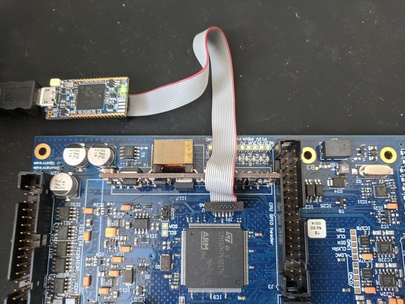
Power up the device and copy dual-iir.bin onto the virtual mass storage ST-Link drive
that has appeared on your computer.
Power down the device before removing the probe, inserting it into the crate
and applying power again.
DFU Upload
If an SWD/JTAG probe is not available, you can flash firmware using only a micro USB cable plugged in to the front of Stabilizer, and a DFU utility.
Note: If there is already newer firmware running on Stabilizer that supports the USB serial interface, there is no need to remove Stabilizer from the crate or disconnect any existing connectors/power supplies or to jumper the BOOT0 pin. Instead, open the serial port on Stabilizer and request it to enter DFU mode:
python -m serial <serial-port>
> platform dfu
After the device is in DFU mode, use the
dfu-utilcommand specified in the instructions below, and the DFU firmware update will be complete.
- Install the DFU USB tool
dfu-util - Remove power
- Then carefully remove the module from the crate to gain acccess to the board
- Short JC2/BOOT with the jumper
- Connect your computer to the Micro USB connector below/left of the RJ45 connector on the front panel
- Insert the module into the crate
- Then power it
- Perform the Device Firmware Upgrade (DFU) with
dfu-util -a 0 -s 0x08000000:leave -R -D dual-iir.bin - To keep the device from entering the bootloader remove power, pull the board from the crate, remove the JC2/BOOT jumper, insert the module into the crate, and power it again
SWD/JTAG Firmware Development
To observe logging messages or to develop and debug applications a SWD/JTAG
probe is required. To use a compatible probe with probe-run connect it as
described above.
- Install
probe-rs - Build and run firmware on the device with
cargo run --release --bin dual-iir
When using debug (non --release) mode, decrease the sampling frequency significantly.
The added error checking code and missing optimizations may lead to the application
missing timer deadlines and panicing.
USB
The USB port can be used to bootstrap Stabilizer and configure all internal settings. This is used to specify a fixed IP address, the MQTT broker address or when operating Stabilizer in standalone mode (i.e. without an ethernet connection or an MQTT broker).
Connect a USB cable and open up the serial port in a serial terminal of your choice. pyserial
provides a simple, easy-to-use terminal emulator:
python -m serial <port>
Once you have opened the port, you can use the provided menu to update any of Stabilizers runtime settings.
Note: Network settings (IP and broker) configured via USB do not take immediate effect but require a reboot.
MQTT configuration
The MQTT broker address is configured via the USB port on Stabilizer's front panel. The address can be an IP address or a domain name. Once the broker address has been updated, power cycle stabilizer to have the new broker address take effect.
Verify MQTT connection
Once your MQTT broker and Stabilizer are both running, verify that the application connects to the broker.
A Stabilizer application dual-iir on a device with MAC address ``aa-bb-cc-00-11-22is reporting its status on thedt/sinara/dual-iir/aa-bb-cc-00-11-22/alive` topic.
In addition to the alive status the application publishes meta information about itself on boot, and telemetry messages
at regular intervals. Once you observe telemetry, Stabilizer is operational.
To observe MQTT messages there are several different options. These are
Always connect to the same broker that the device is connecting to (the one set via the serial terminal connection).
CLI: mosquitto_sub
Tools from the mosquitto project:
mosquitto_sub -t 'dt/sinara/dual-iir/+/#' -h mqtt -v
TUI: mqttui
mqttui -b mqtt://mqtt/
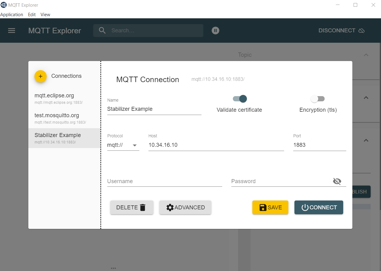
GUI: MQTT-Explorer or MQTTX
Download MQTT-Explorer to observe which topics have been posted to the Broker.
Scraping: telegraf
This telegraf configuration snippet scrapes settings, alive-ness, metadata,
and telemetry from stabilizer/booster/thermostat/thermostat-eem applications.
[[inputs.mqtt_consumer]]
  alias = "miniconf"
  servers = ["tcp://mqtt:1883"]
  topics = [
    "dt/sinara/+/+/telemetry/#",
    "dt/sinara/+/+/settings/#",
    "dt/sinara/+/+/alive",
    "dt/sinara/+/+/meta",
  ]
  data_format = "value"
  value_field_name = "value"
  data_type = "string"  # utf8 json
  name_override = "miniconf"

[[processors.starlark]]
  alias = "miniconf"
  namepass = ["miniconf"]
  source = '''
load("json.star", "json")

def apply(metric):
  if metric.fields["value"] == "":
    return None  # miniconf list/dump/get request, will
  # dt/sinara/{app}/{id}/{class}[/{path}]
  topic = metric.tags.pop("topic").split("/", 5)
  metric.tags["id"] = topic[3]
  metric.tags["class"] = topic[4]
  metric.tags["path"] = "".join(topic[5:])
  v = json.decode(metric.fields["value"])
  if topic[4] == "telemetry":
    metric.name = topic[2]
    for k, v in flatten("", v):
      metric.fields[k[1:]] = v
    metric.fields.pop("value")
  else:
    metric.tags["app"] = topic[2]
    t = type(v)
    if t in ("float", "int", "bool", "string"):
      metric.fields[t] = v
      metric.fields.pop("value")
  return metric

def flatten(k, v):
  l = []
  t = type(v)
  if t == "list":
    for i, vi in enumerate(v):
      l.extend(flatten("%s_%d" % (k, i), vi))
  elif t == "dict":
    for ki, vi in v.items():
      l.extend(flatten("%s_%s" % (k, ki), vi))
  elif t in ("float", "int", "bool", "string"):
    l.append((k, v))
  return l
'''
Within telegraf the mqtt telemetry data can then be routed to e.g. influxdb, prometheus or grafana live.
Usage
Stabilizer supports run-time settings configuration using MQTT or the USB port.
Settings can be stored in the MQTT broker so that they are automatically applied whenever Stabilizer reboots and connects. This is referred to as "retained" settings. Broker implementations may optionally store these retained settings as well such that they will be reapplied between restarts of the MQTT broker.
Stabilizer also supports storing run time settings on the device. Any configurations saved to stabilizer via the USB port will be automatically reapplied when Stabilizer reboots. MQTT settings retained on the broker or settings published after the device has connected to the broker override the settings saved on Stabilizer.
Settings are specific to a device. Any settings configured for one Stabilizer will not be applied to another. Disambiguation of devices is done by using Stabilizer's MQTT identifier, which is defaulted to Stabilizer's MAC address.
Settings are specific to an application. If two identical settings exist for two different applications, each application maintains its own independent value.
Miniconf installation
Create a virtual python environment with python -m venv --system-site-packages .venv and activate it with source .venv/bin/activate.
Refer to the venv tutorial for more information on activating the
virtual environment. The command depends on the operating system.
Next, install prerequisite packages with python -m pip install py/.
To use the miniconf command line too see python -m miniconf --help.
Miniconf also exposes a programmatic Python API, so it's possible to write automation scripting of Stabilizer as well.
Settings
The Miniconf Python utility utilizes a unique "device prefix". The device prefix is always of the
form dt/sinara/<app>/<mac-address>, where <app> is the name of the application and
<mac-address> is the MAC address of the device, formatted with delimiting dashes, and lower case letters.
Settings have a path and a value being configured. The value parameter is JSON-encoded data
and the path value is a path-like string.
python -m miniconf -b mqtt -d dt/sinara/dual-iir/+ stream='"10.34.16.123:4000"'
Where mqtt is the MQTT broker (host name or address) that matches the one used by the application
(set using the USB terminal) and 10.34.16.123 and 4000 are the desired stream target IP and port.
The prefix can be discovered as above or determined for a specific device through the USB serial terminal.
Refer to the application documentation for the exact settings and values exposed for each application.
The rules for constructing path values are documented in miniconf's
documentation
Refer to the documentation for Miniconf for a description of the possible error codes that Miniconf may return if the settings update was unsuccessful.
Telemetry
Stabilizer applications publish telemetry utilizes MQTT for managing run-time settings configurations as well as live telemetry reporting.
Telemetry is defined as low rate, general health information. It is not intended for high throughput or efficiency. Telemetry is generally used to determine that the device is functioning nominally.
Stabilizer applications publish telemetry over MQTT at a set rate. Telemetry data units are defined by the application. All telemetry is reported using standard JSON format.
Telemetry is intended for low-bandwidth monitoring. It is not intended to transfer large amounts of data and uses a minimal amount of bandwidth. Telemetry is published using "best effort" semantics - individual messages may be dropped or Stabilizer may fail to publish telemetry due to internal buffering requirements.
In its most basic form, telemetry publishes the latest ADC input voltages, DAC output voltages, and digital input states.
Refer to the respective application documentation for more information on telemetry.
Stream
Stabilizer supports streaming real-time data over UDP. The stream is intended to be a high-bandwidth mechanism to transfer large amounts of data from Stabilizer to a host computer for further analysis.
Streamed data is sent with "best effort" - it's possible that data may be lost due to network congestion.
Refer to the the respective application documentation for more information.
stabilizer-stream is an application that supports process
the stream and measures power spectral density/integrated RMS in real time.
Crate dual_iir
Expand description
§Dual IIR
The Dual IIR application exposes two configurable channels. Stabilizer samples input at a fixed rate, digitally filters the data, and then generates filtered output signals on the respective channel outputs.
§Features
- Two indpenendent channels
- up to 800 kHz rate, timed sampling
- Run-time filter configuration
- Input/Output data streaming
- Down to 2 µs latency
- f32 IIR math
- Generic biquad (second order) IIR filter
- Anti-windup
- Derivative kick avoidance
§Settings
Refer to the DualIir structure for documentation of run-time configurable settings for this application.
§Telemetry
Refer to stabilizer::telemetry::Telemetry for information about telemetry reported by this application.
§Stream
This application streams raw ADC and DAC data over UDP. Refer to stream for more information.
Modules§
- app
- The RTIC application module
Structs§
- Active
- Biquad
Repr - Channel
- A ADC-DAC channel
- DualIir
- Settings
Enums§
Constants§
Crate lockin
Expand description
§Lockin
The lockin application implements a lock-in amplifier using either an external or internally
generated reference.
§Features
- Up to 800 kHz sampling
- Up to 400 kHz modulation frequency
- Supports internal and external reference sources:
- Internal: Generate reference internally and output on one of the channel outputs
- External: Reciprocal PLL, reference input applied to DI0.
- Adjustable PLL and locking time constants
- Adjustable phase offset and harmonic index
- Run-time configurable output modes (in-phase, quadrature, magnitude, log2 power, phase, frequency)
- Input/output data streamng via UDP
§Settings
Refer to the Lockin structure for documentation of run-time configurable settings for this application.
§Telemetry
Refer to stabilizer::telemetry::Telemetry for information about telemetry reported by this application.
§Stream
This application streams raw ADC and DAC data over UDP. Refer to stream for more information.
Modules§
- app
- The RTIC application module
Structs§
Enums§
- Conf 🔒
- Lockin
Mode 🔒
Constants§
Crate dds
Expand description
Urukul as a downstream EEM on stabilizer.
This requires the alternate direction EEM transceiver configuration. It exposes the Urukul CPLD and DDS settings via miniconf (MQTT and USB).
Note that several values are not range checked and out-of-range values will lead to panics.
Modules§
- app
- The RTIC application module
Structs§
Crate fls
Expand description
Patent pending: DE102021112017A1
§Algorithm description
This application can be understood as a universal phase (frequency) signal processor. It determines the phase (we will drop frequency from now on as in a phase-aware system frequency is merely the difference between successive phases) of an RF input signal and emits an RF output signal with a phase that depends on the input phase. The transfer function between input and output phase is a sequence of various types of filters (analog RC, digital FIR, IIR, unwrapping, scaling, clipping) designed to implement either high-quality phase measurements or a certain constrained and somewhat exotic phase locked loop that is highly applicable to the task of stabilizing the arm length of an optical Michelson interferometer which in turn occurs when stabilizing the effective path length of an optical frequency transmission system.
The sequence of processing steps is as follows. Analyzing it’s application in the context of optical path length stabilization including laser sources, optical modulators, and photodetectors optical is left as an exercise for the user.
§PLL path
- DDS locks its sysclk (500 MHz) to XO or external ref
- DDS emits SYNC signal at sysclk/4
- Prescaler 1/4 (in CPU)
- Drives CPU timer counter
- Counter is captured once per batch (based on CPU clock). See stabilizer::hardware::pounder::timestamp.
- Digital PLL reconstructs SYNC frequency and phase (thus sysclk) w.r.t. batch and sample frequency and phase. This determines the relation of the CPU 8 MHz crystal (thus CPU clock and timers) to the DDS clock (derived from an external reference frequency or internal XCO). See idsp::PLL.
§Signal path
- RF signal enters Pounder at Pounder IN0
- Adjustable attenuation
demod_att. - 30 dB gain block
- Mixing with DDS at
demod_freq - RC lowpass and amplification to reject unwanted demodulation products and harmonics
- IF signal enters Stabilizer and is available at ADC0 for analog monitoring
- 2x PGIA and AA filter on Stabilizer
- ADC digitization at 1/1.28 µs interval
- Data processing in batches of 8 samples
- Digital mixing with the reconstructed sample phase (PLL path). See idsp::Lockin.
- Lowpass filtering with a second order (12 dB/octave) IIR lowpass with an additional double zero at Nyquist. Adjustable corner frequency. See idsp::Lowpass
- Full rate baseband demodulated data (quadrature only) on DAC0
- Lowpass filtering with a batch-size boxcar FIR filter (zeros at n/4 Nyquist)
- Computation of signal power and phase.
- Fractional rescaling (
phase_scale) and unwrapping of the phase with 32 bit turn range. - Scaling and clamping.
- Filtering by a second order (biquad) IIR filter (supporting e.g. II, I, P action). See idsp::iir.
- Clamping, output offset, and anti-windup. See idsp::iir.
- Feedback onto a frequency offset of the modulation DDS at
mod_freq - Additional feedback path from the phase before unwrapping onto the
modulation DDS phase offset with an adjustable gain
pow_gain - Adjustable DDS output amplitude and blanking on digital input
- Adjustable modulation attenuation
mod_att - Modulation output at Pounder OUT0
§Telemetry
Data is regularly published via MQTT. See CookedTelemetry.
§Streaming
Full-rate ADC and DAC data is available via configurable UDP data streaming.
See stream. To view and analyze noise spectra the graphical application
stabilizer-stream can be used.
Modules§
- app
- The RTIC application module
Structs§
- Channel 🔒
- Channel
Config 🔒 - Channel
State - Channel
Telemetry 🔒 - Channel Telemetry, all undersampled and not AA filtered
- Config
- Cooked
Telemetry - Telemetry structure.
This structure is published via MQTT at the
telemetry_intervalconfigured in Settings. - Dds 🔒
- Fls
- Settings structure for the application. All fields in this structure are available through MQTT and can be configured at runtime.
- Settings
- State
- Stream 🔒
- Stream data format.
- Stream
Channel 🔒
Crate mpll
Modules§
- app
- The RTIC application module
Structs§
- App
- Settings
- Telemetry
- Telemetry
Cooked - Telemetry
State - Channel Telemetry